Note
Click here to download the full example code
Manual Sensor Alignment#
This example illustrates the preprocessing pipeline, to make sure that coordinate system conventions are correct for the use of all gaitmap functions.
In many cases manual alignment is the easiest way to get started, if the rough sensor orientation is known. This will be mostly the case for recordings in controlled environments.
If the sensor orientation is not known, you can attempt to use an automatic sensor alignment, explained in the examples Automatic sensor alignment (detailed) and Automatic sensor alignment.
import matplotlib.pyplot as plt
Getting some example data#
For this we take some example data that contains the regular walking movement during a 2x20m walk test of a healthy subject. The sensors were attached to the lateral side of each foot, which means, that the recorded sensor data must be transformed to match the gaitmap coordinate system definitions. The data contains information from two sensors - one from the right and one from the left foot.
from gaitmap.example_data import get_healthy_example_imu_data_not_rotated
from gaitmap.utils.consts import SF_ACC, SF_GYR

example_dataset = get_healthy_example_imu_data_not_rotated()
sampling_rate_hz = 204.8
example_dataset.sort_index(axis=1).head(1)
Rotate to Sensor Frame Definition#
The sensor orientation / coordinate system during the data recording might not match the gaitmap coordinate system definition. Therefore, we have to ensure, that the input data is close to the correct gaitmap definition (here referred to the sensor-frame ) to always start with a harmonised coordinate system definition, which all following gaitmap function will rely on!
Note: This step is specific for each sensor position and might vary from dataset to dataset. Further, it requires knowledge about the approximate mounting orientation of the sensor on the foot. Based on this knowledge it should be possible to achieve a rough alignment with the gaitmap SF. Most of the time this should be solvable by using only multiples of 90/180 deg rotations (provided that the sensor was at least somewhat aligned to one of the foots axis during recording)! Helper functions for this initial alignment are provided in an additional external package called gaitmap-io!
- In the provided example, the two sensors were mounted laterally on the foot. Given a birds eye view of both feet:
The x-axis for left and right foot was pointing “upwards” (parallel to gravity)
The y-axis for left foot was pointing in movement direction “forwards”, while the y-axis for the right foot was pointing opposite to the movement direction “backwards”
The z-axis for left and right foot was pointing “outwards” on the lateral side
This required two independent rotations for the left and the right foot to achieve the alignment. In other cases, a single rotation for both sensors might be sufficient.
# Rename columns and align with the expected orientation
import numpy as np

from gaitmap.utils.rotations import flip_dataset, rotation_from_angle

# rotate left_sensor first by -90 deg around the z-axis, followed by a -90 deg rotation around the x-axis. As the rotation matrix is multiplied from the left, the rotation matrix  results in:
left_rot = rotation_from_angle(np.array([1, 0, 0]), np.deg2rad(-90)) * rotation_from_angle(
    np.array([0, 0, 1]), np.deg2rad(-90)
)

# rotate right_sensor first by +90 deg around the z-axis, followed by a +90 deg rotation around the x-axis
right_rot = rotation_from_angle(np.array([1, 0, 0]), np.deg2rad(90)) * rotation_from_angle(
    np.array([0, 0, 1]), np.deg2rad(90)
)

rotations = {"left_sensor": left_rot, "right_sensor": right_rot}

# As all rotations are just "axis-flips" we can use flip_dataset to apply the rotations, which is much faster than using
# `rotate_dataset`.
dataset_sf = flip_dataset(example_dataset, rotations)
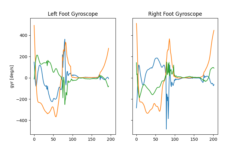
Visualize one “left” and one “right” stride, and compare the individual sensor axis to the gaitmap coordinate system guide. Axis order and axis sign should match gaitmap coordinate definitions. Note that for the sensor-frame, signs will differ for the left and the right foot!
_, (ax0, ax1) = plt.subplots(1, 2, sharex=True, sharey=True, figsize=(8, 5))
ax0.set_title("Left Foot Gyroscope")
ax0.set_ylabel("gyr [deg/s]")
ax0.plot(dataset_sf["left_sensor"][SF_GYR].to_numpy()[585:780, :])

ax1.set_title("Right Foot Gyroscope")
ax1.plot(dataset_sf["right_sensor"][SF_GYR].to_numpy()[475:678, :])
plt.show()
Align to Gravity#
Although we already rotated our initial data somewhat close to the gaitmap coordinate system we still need to make sure that the z-axis is aligned with gravity (defined by [0,0,1]) as required by the gaitmap sensor-frame definition. Therefore, we will use a static-moment-detection, to derive the absolute sensor orientation based on static accelerometer windows and find the shortest rotation to gravity. The sensor coordinate system will be finally rotated, such that all static accelerometer windows will be close to acc = [0.0, 0.0, 9.81]. If the default parameters for this function will not work out for your specific dataset, please refer to the troubleshooting section below for more information!
from gaitmap.preprocessing import sensor_alignment

dataset_sf_aligned_to_gravity = sensor_alignment.align_dataset_to_gravity(dataset_sf, sampling_rate_hz)
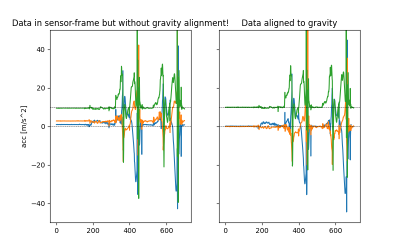
Visualize the result of the gravity alignment
_, (ax0, ax1) = plt.subplots(1, 2, sharex=True, sharey=True, figsize=(8, 5))
ax0.set_title("Data in sensor-frame but without gravity alignment!")
ax0.set_ylabel("acc [m/s^2]")
ax0.plot(dataset_sf["left_sensor"][SF_ACC].to_numpy()[:700, :])
ax0.axhline(0, c="k", ls="--", lw=0.5)
ax0.axhline(9.81, c="k", ls="--", lw=0.5)

ax1.set_title("Data aligned to gravity")
ax1.plot(dataset_sf_aligned_to_gravity["left_sensor"][SF_ACC].to_numpy()[:700, :])
ax1.axhline(0, c="k", ls="--", lw=0.5)
ax1.axhline(9.81, c="k", ls="--", lw=0.5)
ax1.set_ylim([-50, 50])
plt.show()
Troubleshooting#
The align_dataset_to_gravity function might fail to find static windows within your input signal and therefore might also fail to align your signal. In this case you might need to tweak the default parameters a bit:
First you could try to increase the threshold: The threshold refers to the metric calculated over the given window on the norm of the gyroscope. So given the default metric “median” this means, a window will be considered static if the median of the gyroscope norm is lower than the given threshold within the window length.
Second you could try to lower the window length: The shorter the window length, the higher the chance that there is sequence of samples which will be below your set threshold.
These two options can be adapted using the parameters window_length_sec, static_signal_th and metric.
dataset_sf_aligned_to_gravity_ = sensor_alignment.align_dataset_to_gravity(
    dataset_sf, sampling_rate_hz, window_length_s=0.5, static_signal_th=3.5, metric="median"
)
Total running time of the script: ( 0 minutes 1.393 seconds)
Estimated memory usage: 13 MB